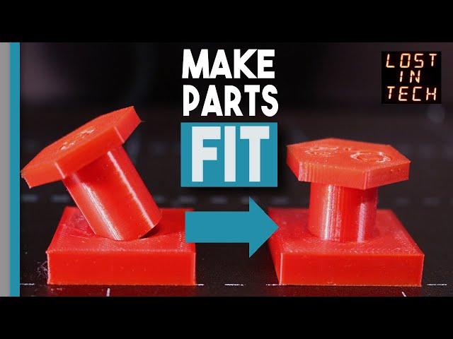
Why your 3d printed stuff doesn't fit together and how to fix it!
Комментарии:

lmao trigger warning. ill watch someone elses guide thanks
Ответить
I'm printing outer walls first and running into the exact same issue where models don't fit together appropriately. Other people aren't having issues. What then? My Z offset is perfect, my temp is perfect, strings are perfect, rails perfect, leveling perfect. AND I'm an engineer. The only thing I can think of is that some printers have wildly varying accuracy.
Ответить
There is an easier way to test.
- print a 5mm hole and a 5mm peg
- use a caliper to measure each and note the change
- adjust your CAD drawing
- print
Keep the measurements to adjust future designs.

In 3D printing, round pegs don't even fit into round holes. Oversize your hole, make it square, and use tons of glue. Tada!
Ответить
There's just another thing to add: when you generate your .stl file exported from a parametric 3d model software (like solidworks, fusion and inventor) set a good resolution for angles and curves but beware of the file's size.
Ответить
I am so confused, i have printet your model witch is awsome and found a tollerence i "like" but i have no idea how i can get a number out of it or where to insert it in superslicer :S can you dumb it down for me in some way? I think ive seen this video 15 times and i still dont get that part.
Ответить
i have no idea how ur tool works but i made my own inspired by this, using only one peg and then i can see what kind of tolerance i want. and now i can fall back on it if i ever decide i want a tigher fit or not
Ответить
Someone needs to manufacture the fit check test tool so you can test fit with the printer pegs.
Ответить
glorious analogies
Ответить
My experience with modeling is that I usually get the correct sizes when I design internal dias bigger by a half nozzle dia and external by a half smaller. Interference fit between printed parts I try to avoid if the internal part is not printed in another plane. When they are both in the same plane I usually design them with a gap and fill the gap with epoxy if it is a permanent connection. I found nice products designed by the engineers that fit on first print, but they use tolerances, and tolerances table suggests bigger gaps on larger parts and if they implement the tables correctly the take into account variations made by a standard nozzle, which I usually do not do. My brain works in absolute measures, and that is not good, it is even worst when designing a part for metal cnc or lathe.
Ответить
As an engineer, the way you said things is on point. Sure, clearance and tolerance are in fact different concepts but that's a tangent irrelevant to the topic, which I certainly must add, you explained perfectly.
That clearance gauge you designed is totally genius, and I'd think that dialing the settings on the printer perfectly for it to have precise measures according to the clearance increments, would result in an even better way of finding out material dilatation or contraction percentage once the square and pegs are printed, and the gauge would need to be printed only once, as you mentioned, and it would kill two birds with a single stone; settings for a material would be known, and that would be the reference point for others.

Don't forget to tune the flow rate
Ответить
I had two machines, which had different X Y tolerance, so we maybe need to test and know every 3D printer as you have, if you need a very low tolerance print ^^
Ответить
For precision fits, I chase the hole with a drill. Same with threads, print to get them close, then chase with a thread cutter.
Ответить
nice, remember: tolerance ≠ clearance
Ответить
I add or subtract.3 to .5 mm on the dimensions one one of the 2 parts to compensate and they always fit and have accuracy
Ответить
hello, great video, thanks :) 👍
Ответить
I wonder if anyone else is having problems with Thinkiverse right now?
I went to the link and of course, it asks me to log in. The auto fill did not have my correct PW, so that failed, which is fine.
But when I put in the right PW, it looked like it was logging in and I was able to download the gauge.
However, it still says, "Sign up" rather than showing my thumbnail to show that I'm logged in.
This site seems to have so many problems for years. Remember when it was so slow that it was impossible to use and how often people had problems to upload or download.... ? sigh...
Oh well... at least I got this gauge, which I think is a brilliant idea.
I have a Wanhao Duplicator 9, MK2 400, which is super difficult to get to print accurately. Even after going through very tight fine tuning. But now I wonder if THIS, as mentioned in this video, might be part of the problem.
Let the testing begin. LOL

By modelling I started with a tollerance the same size the nozzle is. This works the most time 😅
Ответить
I constantly design and print my own parts. The sweet spot I have landed on to get a snug but not sloppy fit is 0.2mm.
This is specifically for threaded parts like screws and corresponding fasteners. the screws are almost always 100% infill as are the fasteners at 0.1mm layer height.
Most of this is printed in PLA/PETG/PC/Nylon
ABS is just too inconsistent.

I just printed a cube with the size of 1 cm, and then measured it with digital calipers. In multiple spots, to be certain and average the result. That extra measured portion is essentially the clearance you'll need. So if you measured 10.8 mm, you need to shrink your parts inwards by 0.8 mm, and they will fit after being printed*.
*The remaining issue is the elephant's foot.

Making round and sqare holes perpendicular to the printing surface is the easy part. Doing same with and angled makes printing the right size even more complicated. So how you make threads then? Threaded holes and outerthreads? On my printer i make screws and threades holes from M10 up to unlimited which workds pretty well when i make the holes 0.2mm bigger and the screws 0.2 mm small with a 0.4 nozzle and PLA+ or PETG. But modelling these threads is not trivial because you have to force the cad system to make M 16.2 or M15.8 Threads which is not easy to get. And to even push it higher try to make conical pipe threads, here common cad systems are giving almost no support so you have to model those threads completly manually which needs strong skills in modelling freeformsurfaces.
So i would like to see this in you next video and how you will fix it that 3d printed threads will fit together!

Make fart pits
Ответить
you just earned urself a new subscriber. cheers!
Ответить
i had to inlay some letters into a piece before and it was a pain in the butt to get them pressed in. as true as it is about corners, i just got a razor blade and trimmed it down, as for round prints, ive actually had quite a problem printing them, usually sanding them down works intill you get a size/shape where you cant get sandpaper in. again like the letters i had to inlay. if i were to do it again, sure i would try to fine tune everything, but i would probably still have to brute force them in
Ответить
Good K value to start with Sovol SV06?
Ответить
Thanks for the tool. Often use SV06 and Prusa Mini together on the same project.
Ответить
I always do the following: instead of a square or round solid peg, design it as a flexible two-pronged peg which can be compressed in one dimension. Think of it as two banana-shaped prongs, with their widest parts a bit wider than the hole. When inserted in the hole the two parts will bend slightly, and will provide good frictional fit with the other part. The larger you make the hole and banana-peg, the more friction you can produce.
Ответить
About corners:
Do we really need rectangular designs?
We usually have rectangular shapes because flat surfaces are easy to manufacture and assemble at scale.
Small elements are better with curved edges - it makes them more rigid, hard and precise.
We cant actualy mold a perfect square either. It can only be cut.
What i want to say:
FDM printer is not the problem - our designs are!
We need to learn to use advantages and avoid faulty designs.

I just simply print a tolerance test bar with a hole bigger than a cylinder and square by 0.15 mm, 0.2 mm and 0.25 mm.
Then I try to fit the cylinder in it and ajust the model how I want it to be. I do that for every type of new fillament.
It's very easy to adjust the vertices in Blender afterwards.
However, it's kinda worsen if the object gets larger in width and length.

Tolerance aside, when designing parts to fit in one another I've had success minimizing surface area of the contact. if a square goes in square, chamfer the male part so you don't have to worry about corners. If a round goes in round, flute the male round to create gaps without friction, think of a cylinder on a revolver. Also consider the use case, I've made parts with zero tolerance where I expect to lightly tap the parts together and never remove them. On the other hand, a box and lid will need a tolerance so the lid can go on and off the box when needed.
Ответить
I think the issue with a percent scale gauge is that depending on the size of your peg/hole the percentage will change the clearance by a different amount.
1% of a 10mm hole is different than 1% of a 50mm hole.

Just use proper software to generate gcode ;)
Ответить
Depending on what it needs to fit, I make it tight fit, and then sand or drill away excess
Ответить
Humidity of the filament has a lot of impact on the tolarence
Ответить
You could always just sand down the pegs
Ответить
I would suggest adding a feature to the pegs to indicate their X-Y print orientation. That would allow the user to diagnose X vs Y axis fit issues if they are present. Good job.
Ответить
Its so worth the work to get that interference fit. It's so satisfying when 2 parts snap together perfectly and holds there.
Ответить
"Pushing Plastic" would be a great name for a channel
Ответить
I feel like slicers should easily be able to compensate for the material being pushed out when printing the inner perimeter first...
Ответить
Most of the parts I print are cases I design myself for various sorts of circuit boards, and my preference is for an interference fit so I can just snap the lid on. With my printer (a heavily modified Ender 3) and preferred filament (Duramic PLA plus) I have found that a 0.2mm clearance works consistently. To avoid the issue with the corners, I always put either a 0.5 or 1mm chamfer on all external corners (ie the outside of a peg, not the inside of a hole) which both gives a better fit, and at least to me gives a part that looks more professional.
Ответить
this is why i work with metal
Ответить
Can't go wrong with GO/NO GO gauges especially when there are so many variables when 3D printing, excellent idea!
Ответить
Thanks for the video and the explanation. I did print it and tested it out, it definetely is a great way of controling your dimensional accuracy. Liked and subbed!
Ответить
if you're printing in PLA +.02 is your sweet spot
Ответить
this has been a thorn in my side recently, but i have a resin 3d printer and most of the tolerance guides talk specifically about filament printers. even the new benchy test print engine works by laying a bead across left over filament strands which resin printers simply cant utilize. does anyone have a recommendation or a test print for pin/hole tolerances for resin printers?
Ответить


![The Prodigy - Live @ Brixton Academy & Wembley Arena, London, UK (Concert-Compilation) [2008 - 2009] The Prodigy - Live @ Brixton Academy & Wembley Arena, London, UK (Concert-Compilation) [2008 - 2009]](https://ruvideo.cc/img/upload/TWVOZzFkSVg3aXI.jpg)


