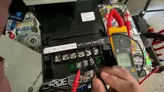
HOW TO TEST IF A VFD ( Variable Frequency Drive ) IS BAD WITH A MULTIMETER
Комментарии:

Thank you
Ответить
Can you speak up I can't couldn't hear.
Ответить
that would be "transistor" not transmitter for IGBT, and thanks for the video
Ответить
Thanks bro for the info and time share
Ответить
Do you use positive to negative dc and positive dc to negative terminal
Ответить
Im still confused on why you're testing between AC and DC. I understand the drive is converting the AC to DC, and then back to AC. But its done all internally. Aren't those DC terminals used for 24v for the drive? I guess i just don't understand the relationship between the AC and DC terminals.
Ответить
Great video! Thank you for sharing.
Ответить
Its not really AC but Pulsed DC that goes into the motor.
Ответить
Nice 👍 definitely needed to see this video thanks man
Ответить
I thought when the neg probe is on DC- it should be infinity? Shouldnt you see numbers/measurements at first until it hits O/L?
Ответить
why negative is ol negative to negative
Ответить
Great video
Ответить
Why you choose negative frim drive to make check with l1 l2 l3 and u v w ?
Ответить
👍👍👍
Ответить
I dont understant why your not using the diode feature of that meter to do the troubleshooting.
Ответить
The video is not bad but I literally don't understand everything..
Ответить
I can not hear your voice. Increased volume
Ответить
Negative or positive meter leads shouldn’t matter where you put on terminals if it’s selected on OHMS.
Ответить
A&B were best in class for training & tech support. Years ago I attended a week training at Allen Bradley for a special VFD that was only used on a few thousand Goss RTP'S ( Reel Tension Posters ) for 2,500# rolls of newsprint. The VFD had a program that calculated the speed of expiring roll of paper and perform an exact speed match on paper that could be traveling more then 25 miles per hour ( press running at 50,000 papers per hour ). Was amazing to watch paper being cut then pressed down on fast moving g paper. A&B has great products & great tech support. While our 20 special A&B were under warranty and we were having major problems with a couple of them they were going to fly out a tech but they fixed it over the phone.
Ответить
Place that I retired from had over 100 ABB 6 & 18 pulse drives. We had about 45 5 HP garbage ABB drives in a 5 story garage that over 25% burnt up first year. Told us they are throw always and have to purchase new ones. ABB tech support were prima donnas that always gave me a hard time when I only asked them 1 or 2 questions. A&B & Danfoss tech support were best in class.
Ответить
Easy way is remove three out put wires that goes to motor and start the vfd. If vfd is giving out put voltage means vfd is ok if still vfd faulted out at ground or other fault then vfd is bad otherwise motor or cable that is connected to motor
Ответить
The diode check is always the first thing to be done because shorts on the input side or sometimes even the output side cannot be saved by the drive just faulting. What you are actually checking are the 6 input rectifiers as well as the 6 reverse polarity freewheeling diodes built into the modern IGBT's.
What you do is follow the current path from the meter through the component. When you place the negative meter probe on the DC bus Negative, then the positive on any of the inputs or outputs, you are reading OL because you are charging the bus capacitors with the output voltage of the meter. This is what you want to see. When you place the negative meter probe on the DC Positive and then put the positive on any of the inputs or outputs, you are then measuring the drops of all the diodes in the corresponding half of the drive. The three input rectifiers on the 'top', and the three reverse polarity diodes on the IGBT's on the 'top'. When you reverse the probes (positive of meter to DC bus Neg) and do the same operation, you are then measuring all 6 diodes on the bottom half. So you want to see healthy voltage drops typical of those rectifiers, such as above ~300mV or so. Anything below would indicate one of those diodes has failed shorted, and something is going to blow up either powering it up, or giving a run command (if it can't just fault).

Wilson George Thompson Sharon Moore Elizabeth
Ответить
Clark Patricia Hall Daniel Taylor Cynthia
Ответить
Can this way of troubleshooting be done while the vfd is still installed in the machine with the main power off obviously?
Ответить
Excellent tutorial J !
Ответить
A...B...C..?
Ответить
For checking , do i have to remove all the wire OR i can do with wires out
Ответить
Great Video. Thank you.
Ответить
thanks bro
Ответить
Final out is a modified AC .on final output IGBT is insulated gate bipolar FET . Not a transmitter but a gated transistor..Allen Bradley does not want techs inside that drive, tr puling one apart. You got shorted diodes & probably blown fets, Transistors, not transmitters. Another test, put power on it put} your meter on UVW and see if you got output {Sir you dont know your components.] You SS_hit your hat ?
Ответить
It doesn’t go from DC to AC it’s a simulated AC
Ответить
IGBT is Insulated-Gated Bipolar Transistor
Ответить
I'm getting into more vfd troubleshooting work recently, thanks for this. So I'm guessing it looks like the diodes are 'leaking current backwards"?? I don't have any theories on how water exposure did that but did this present as a fault code on the VFD? Or did it just stop working totally? Thanks again!
Ответить
What about the precharger
Ответить
Mine doesn’t have dc positive and negative
Ответить
Cam across this video and I have had 2 of these exact drives go bad in the exact same way
Ответить
I hear David Gilmour in the background
Ответить
Rockwell automation.
Ответить


