Комментарии:

Fantastic explanation.
Ответить
That's not all that complicated. Throw in a few capacitors a couple of inductors and a transistor plus a diode or two for good measure. If you really want to get fancy a quartz crystal and a PTC resistor tossed in should light up your day. Such circuits exist.
Ответить
Your thought me something that my professor couldn't
Ответить
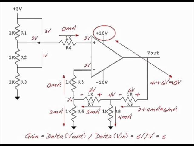
I might be a little bit too late to join the party 😄 I appreciate the clear explanation and detailed solution you provided. Sometimes we all forget that electronics is not that complicated and that all circuits can be handled by simply adhering to a few basic laws. I have a question, and I would greatly appreciate it if you could help me understand the design decision: what is the purpose of R4 and R5 in this circuit?
Ответить
Very good, Dan!
Ответить
Hi Dan, I am delighted with this logic. I don't understand why degrees don't teach this way?! Thank you. I haven't checked the other videos but are there different config which uses L and C?
Ответить
Unfortunately, only stable, negative feedback loop configurations are shown in this explaination. Other configurations are not even mentioned, making the missleading and false claim that the rules shown always apply.
Ответить
Im sorry but i dont understand the first step. I get why R4 has no current flowing through it, but why is VR1 and VR2 equal to 1 volt? How can you determine that the voltage drop between the 3v node and R4 is 2v? Thanks!
Ответить
THANK YOU SIR YOU ARE THE BEST
Ответить
You don't explain this very well. I can't follow
Ответить
I wish you had more of these, but then again, this video was a quantum leap in my understanding of op amps
Ответить
I can't say it any better that the gentleman Sai Sivaram, just below me. Brilliant!
Ответить
Greate explanation, Sir!
Ответить
Excellent. We need simple numbers when first learning about this.
Ответить
Great job!
Ответить
✅💯
Ответить
Really great explanation of working through this op-amp circuit. Thank you very much for taking the time to do this. Cheers
Ответить
Nice! What a nice way of explaining op-amps! Loved it.
Ответить
Excellent video, clear and concise!
Ответить
Thanks, a very helpful video. But could someone explain the purpose of R4 & R5 or are they simply not needed if there's no current flowing through them and no voltage drop? Thanks in advance.
Ответить
Awesome!
Ответить
Good stuff :-)
Ответить
holly crap!! compair this to the video by the indian proffesor at MIT This is now too easy. Thank you sir
Ответить
i didnt get how you assumed the other two input nodes to be 2v and 1 v respectively
Ответить
Rule 2 only works if there is negative feedback. Otherwise, you can put whatever voltages you want on the pins. Remember this.
Ответить
For some reason, this video I stumbled upon at 3am on (another) sleepless night has just hit the spot. You always just find these videos that either repeat things you already know, or are beyond comprehension complicated and you are lost in the first two minutes.
There are always these thoughts where I think „yeah it probably works like that“ but I just never really believe it until someone says it out.
This Video cleared a LOT of those up.
Thank you so, so much.

Nice info, thanks :)
Ответить
best explanation thank you
Ответить
Can u make videos on solving cmos/pmos configurations
Ответить
The way you did this numerical is fantastic and probably the best
Ответить
Good
Ответить
WOW! Absolutely amazing tutorial. I'm currently back in school as a non-trad, and we're working with OpAmp circuits in my upcoming Electronics lab, and when I heard that that would be our second lab, I thought 'ACK! I don't know much about OpAmps, other than that they can be a big stumbling block', and having watched this, I feel much less intimidated. Thank you so much for posting this, this is absolutely amazing, and I'll probably be coming back to your channel as the semester goes on!
Ответить
Thank you very much 👍🏻
Ответить
Thanks for the help
Ответить
if no current goes in the inputs then what's with the 1k/R4?
thanks

This is a great video and you have a talent for conveying challenging concepts. It would be wonderful if you created more videos like this about analog electronic circuit design!
Ответить
THANK YOU!
Ответить
but how can there be no current in the input?
Ответить
Rule 2 applies only in negative feedback connection. Not for schmitt trigger configuration with positive feedback. Otherwise thumbs up
Ответить
well done, dude!
Ответить
Could you confirm what ground you would be referencing from if probing the inputs/output given that the rail is in the minus please. Would it be taken from the minus rail to the op amp. or from power supply ground.
Ответить
Since the inputs were not equal when switch was at 3V, there was a difference in voltage between the input terminals. Does that mean that the last calculations would be wrong since current would be flowing out of the inverted input? Or is input impedance so high that there would still be no current flow?
Ответить
Excellent Sir. So far I haven't seen someone mentioning rule 3.
Ответить
Posted 8 years ago and it is more helpful than other sources i have been read and watched. Thank for this video I learned a lot about op amp
Ответить
My my it's really a good insight to use opamps for many different things. Thank you.
Ответить
Good video but the volume is a bit low.
Ответить
This is the first time I've fully understand how op amp works. Thanks a lot!
Ответить
I love this video - very helpful - thank you Sir!
Ответить


